The core of the CAD tool is based on computing blocks consisting of two different external software packages utilizing different mathematical algorithms. Provisions have also been made for the independent connection of computing modules made by other specialists. Preparation of data, management, and assessing the results of calculations made are all accessible regardless of the type of the computing module.
“A knowledge of modern technologies wasn't enough when it came to developing Sphere – it also required qualified management. The company's leadership and specialists managed to cope with this challenging task.”
The graphic system for analysing electrical supply networks is based on all the experience gained from using old school GUI-free software package, and provides a modern, user-friendly graphic interface, containing many new features and capabilities. The programme is set up to analyse historical, current and projected operational setups in electrical power supply networks, including assistance in preparing for changeovers in the provision of electricity, including the implementation of the changeover itself and the modifications to the operational process. The programme allows for evaluation and analysis of the electrical supply regime through the use of third party computing modules.
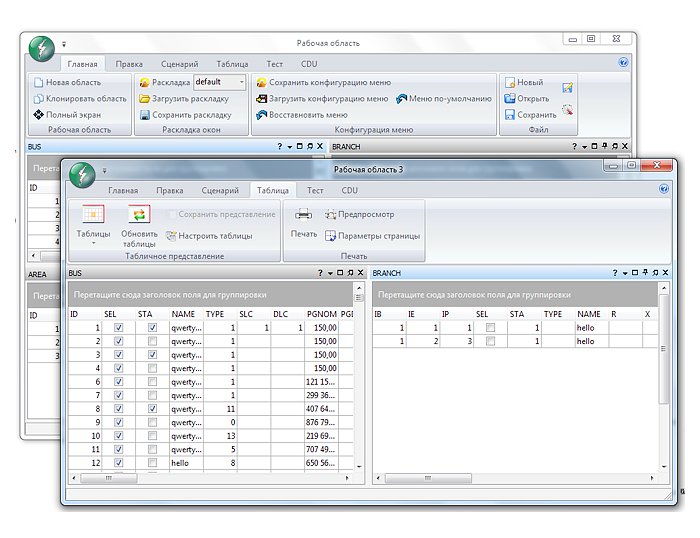
CAD tool includes a modern main menu interface with a quick access panel and dynamically active banner menu.
Software features
- Export and import of models, data and calculations
- Automatically carrying out calculations
- Multiple tables can be opened so that data from successive calculations can be compared
- Data can be introduced and edited quickly and in an effective manner
- A scripting subsystem has support for various programming languages for making calculations
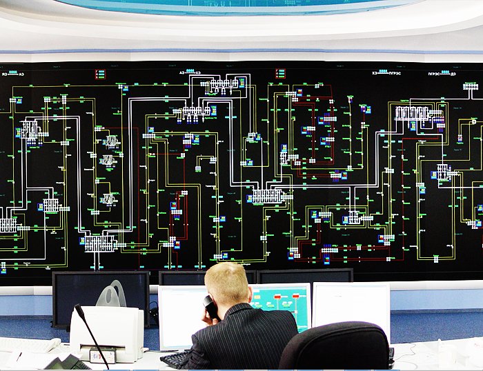
The software solution contains a powerful display system based on Windows Presentation Foundation. The graphic display is built so as to show information for individual facilities and electrical systems – diagrams and maps are graphically assisted by values, symbols and data tables for integrated analysis.


 2002–2025